

Currently Empty: $0.00

Night-light: LED turns ON when it’s dark.
Introduction
In this first build we meet the LDR, a resistor whose value drops in bright light and rises in darkness. We’ll pair it with a fixed resistor to create a voltage divider—two resistors in series between +5 V and ground. The midpoint voltage becomes our light signal. When the room is bright, the LDR’s resistance is low and the midpoint moves toward +5 V (or toward GND if the LDR is on the bottom). We’ll tap that node to drive an LED through a current-limiting resistor. The goal is to see the physics: more light → more/less LED brightness depending on where we place the LDR, and we’ll log current to prove it.
Hardware Required
- LDR senor (≈5–10 kΩ in bright light; 100 kΩ–1 MΩ in darkness)
- Breadboard
- Jumper wires
- Resistors: 220–330 Ω (for LED), 10 kΩ, 47 kΩ (as needed)
- LED (5 mm)
- Power supplies: 5 V
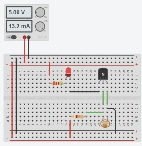
Circuit
- Power off. Pick the red rail as
+5 Vand the blue/black rail asGND. - Place the LDR vertically across one breadboard gap so each leg sits in a different row.
- Add a 10–47 kΩ resistor from the lower LDR leg to
GND. Now you have+5 V → LDR → node → resistor → GND. - Jumper
+5 Vto the upper LDR leg. - This junction between the LDR and resistor is the signal node. Put the LED anode (long leg) in that node, and the LED cathode into a 220–330 Ω resistor that goes to
GND. - Power on at
5.0 V. Wave a hand over the LDR. Observe and call out what happens to LED brightness and supply current. - If the LED behavior is inverted, swap the positions of the LDR and the fixed resistor (put LDR to
GND, resistor to+5 V). Discuss how divider orientation flips the behavior.
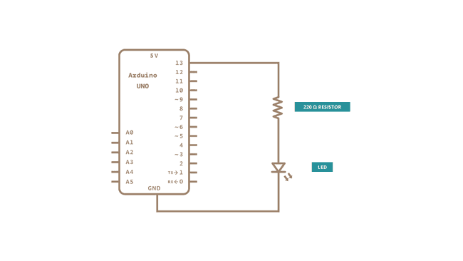
Schematic Diagram
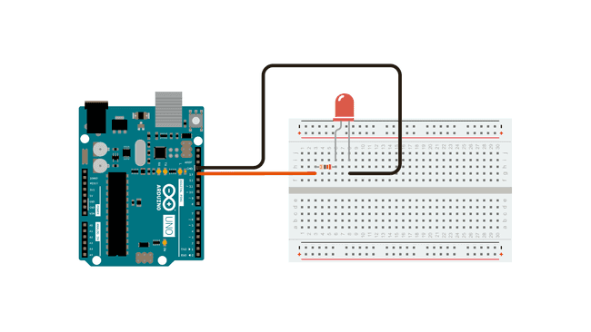
The circuit for this project is simple yet essential for understanding how Arduino controls physical components. The LED is connected so that its anode (long leg) receives current from Arduino’s digital pin 13, while its cathode (short leg) is connected to the ground (GND). Between the LED and the pin, a 220Ω resistor is placed in series to limit the flow of current and prevent the LED from burning out. When pin 13 is set to HIGH (5V), current flows from the Arduino through the resistor and LED into ground, causing the LED to light up. When the pin is set to LOW (0V), no current flows and the LED turns off. This simple circuit demonstrates how Arduino can act as a switch, controlling whether current flows or not, and is the foundation of many more complex electronic projects.
Troubleshooting
-
LED always ON
- Likely causes: Divider inverted vs expectation (LDR on bottom); LED wired directly to
+5 V; short at signal node. - Fixes: Swap LDR and fixed resistor positions in divider; verify LED is in series with 220–330 Ω to
GND; recheck node wiring.
- Likely causes: Divider inverted vs expectation (LDR on bottom); LED wired directly to
-
LED always OFF
- Likely causes: Open circuit (loose jumper); LED reversed; wrong resistor value (e.g.,
220 kΩinstead of220 Ω); no5 Vsupply. - Fixes: Tug-test jumpers; flip LED orientation (long leg to node); confirm resistor values by color bands; verify
+5 VandGNDrails.
- Likely causes: Open circuit (loose jumper); LED reversed; wrong resistor value (e.g.,
-
LED changes only slightly with light
- Likely causes: Divider impedance too low/high relative to LDR range; LDR placed where room light is uniform.
- Fixes: Try 10 kΩ–47 kΩ for the fixed resistor; reposition LDR; shield from ambient or use a flashlight to test range.
-
Supply current too high
- Likely causes: Missing LED series resistor; short across rails.
- Fixes: Ensure 220–330 Ω in series with LED; inspect for a jumper bridging
+5 VtoGND.
-
Opposite behavior than expected (bright → dim or dark → bright)
- Likely cause: LDR position in the divider sets polarity.
- Fix: Put LDR at top (to
+5 V) for one polarity, bottom (toGND) for the other.
Tinkercad Simulation
You can simulate the Level 1 version of the above project in Tinkercad here: Level 1 Simulation . Open it to interact with the LDR–resistor divider, adjust the light slider to see the LED brighten/dim, and verify correct wiring (LED with a 220–330 Ω series resistor). You can also probe the signal node voltage and try swapping the LDR and fixed resistor to observe how the behavior flips.
Learn more
Night-light with adjustable sensitivity (potentiometer)
Introduction
In Level 1 the divider value was fixed, so the ‘just-on’ point depended on the room. Today we add a potentiometer so we can tune sensitivity and set a repeatable threshold. By moving the wiper, we change the bottom resistor value (or create a separate reference), sliding the node voltage up or down until the LED flips at the exact light level we want—like setting a night-light to come on at dusk.
Hardware Required
- LDR sensor
- LED
- Resistors: 220–330 Ω
- Potentiometer: 10–100 kΩ
- Power supply: 5 V
- Breadboard
- Jumper wires
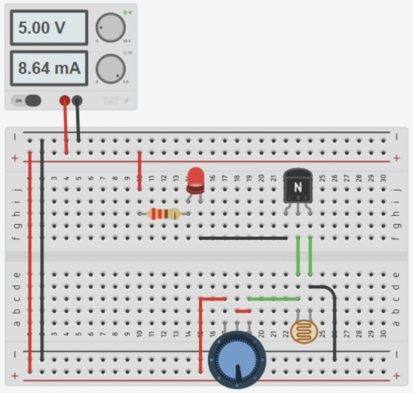
Circuit
- Power off. Remove the 10–47 kΩ fixed resistor from Level 1.
- Place a 10–100 kΩ potentiometer so each of its three pins sits in a separate breadboard row. Identify the wiper (middle pin).
- Connect the wiper to the signal node under the LDR.
- Connect one outer pin of the potentiometer to
GND. Leave the other outer pin unconnected (or tie it to the wiper to make a 2-terminal variable resistor). - Double-check the divider path:
+5 V → LDR → node → pot (wiper → GND). - The LED path remains:
node → LED → 220 Ω → GND. - Power on. Rotate the knob slowly. Find the point where the LED just turns ON in darkness and turns OFF in bright light. Mark the pointer position with a pen.
Schematic Diagram
aaa
Troubleshooting
-
No change when turning the potentiometer
- Cause: Wiper not connected to the node; wrong pot pins; dead pot.
- Fix: Ensure the middle pin (wiper) goes to the sensor node; one outer pin to
GND; test the pot with a DMM for varying resistance.
-
LED flickers near a certain knob position
- Cause: Threshold sitting exactly at ambient light; minor hand shadows cause oscillation.
- Fix: Nudge the pot slightly; add a small capacitor (e.g., 100 nF) from node to
GNDto smooth; adjust lighting.
-
LED turns ON only at extremes of the knob
- Cause: Pot value not in a good range for the LDR; divider ratio never crosses LED-visible region.
- Fix: Use a 10–100 kΩ pot; try swapping LDR top/bottom; change the pot to a value closer to typical LDR dark resistance.
-
Very dim LED even when “ON”
- Cause: Node voltage never high enough; LED still directly loaded by divider; series resistor too large.
- Fix: Reduce LED series resistor to 220 Ω; ensure node reaches a few volts in dark; consider moving to Level 3 transistor buffer.
-
Random behavior when touching the pot
- Cause: Floating terminals or poor breadboard contacts.
- Fix: Tie the unused outer pot pin to the wiper (use as 2-terminal variable resistor) or leave cleanly unconnected; reseat parts.
Tinkercad Simulation
You can simulate the Level 2 version of the above project in Tinkercad here: Level 2 Simulation . Open it to interact with the LDR–resistor divider, adjust the light slider to see the LED brighten/dim, and verify correct wiring (LED with a 220–330 Ω series resistor). You can also probe the signal node voltage and try swapping the LDR and fixed resistor to observe how the behavior flips.
Learn more
Day-light switch variant (LED ON in light, OFF in dark) using swapped divider
Introduction
The Intermediate project is the “Hello World” of Arduino. Just as a beginner programmer’s first task is to make a computer print “Hello World,” in electronics the first step is making an LED blink.
This project helps you understand the three most important concepts in Arduino programming and electronics:
1. Digital Output – how a microcontroller pin can send a HIGH (5V) or LOW (0V) signal.
2. Timing Control – using the delay() function to pause the program.
3. Circuit Control – connecting a simple circuit with a resistor and LED, and controlling it through code.
By completing this project, you will learn how hardware (the LED circuit) and software (the Arduino code) work
together. This forms the foundation for controlling sensors, motors, and other components in future projects.
Hardware Required
Arduino Uno (or compatible board)
• 1 × LED (any color, 5mm)
• 1 × 220Ω resistor (limits current, prevents LED damage)
• Breadboard
• Jumper wires
• USB cable (to connect Arduino to computer)
(Tip: If you don’t have these, you can use the onboard LED already connected to pin 13 on most Arduino boards.)
Circuit
The circuit for this project is simple yet essential for understanding how Arduino controls physical components. The LED is connected so that its anode (long leg) receives current from Arduino’s digital pin 13, while its cathode (short leg) is connected to the ground (GND). Between the LED and the pin, a 220Ω resistor is placed in series to limit the flow of current and prevent the LED from burning out. When pin 13 is set to HIGH (5V), current flows from the Arduino through the resistor and LED into ground, causing the LED to light up. When the pin is set to LOW (0V), no current flows and the LED turns off. This simple circuit demonstrates how Arduino can act as a switch, controlling whether current flows or not, and is the foundation of many more complex electronic projects.
Schematic Diagram
The circuit for this project is simple yet essential for understanding how Arduino controls physical components. The LED is connected so that its anode (long leg) receives current from Arduino’s digital pin 13, while its cathode (short leg) is connected to the ground (GND). Between the LED and the pin, a 220Ω resistor is placed in series to limit the flow of current and prevent the LED from burning out. When pin 13 is set to HIGH (5V), current flows from the Arduino through the resistor and LED into ground, causing the LED to light up. When the pin is set to LOW (0V), no current flows and the LED turns off. This simple circuit demonstrates how Arduino can act as a switch, controlling whether current flows or not, and is the foundation of many more complex electronic projects.
Code with Step-by-Step Explanation
After you build the circuit, plug your Arduino board into your computer, start the Arduino Software (IDE), and enter the code below. You may also load it from the menu:
File → Examples → 01.Basics → Blink.
/*
Blink
Turns an LED on for one second, then off for one second, repeatedly.
*/

// Create a variable for the LED pin
int ledPin = 13; // Built-in LED pin on most Arduino boards

void setup() {
 // This runs once when you power or reset the board
 // Initialize pin 13 as an output pin
 pinMode(ledPin, OUTPUT);
}

void loop() {
 // This runs continuously in a loop

 digitalWrite(ledPin, HIGH); // Turn LED on (apply 5V)
 delay(1000);               // Wait 1 second (1000 ms)

 digitalWrite(ledPin, LOW); // Turn LED off (apply 0V)
 delay(1000);              // Wait 1 second
}
Line-by-Line Explanation
int ledPin = 13; → Defines the LED pin. Pin 13 is chosen because Arduino boards have an onboard LED
connected there.
• void setup() → Runs once at startup. The first thing you do is to initialize the LED pin as an output using:
pinMode(LED_BUILTIN, OUTPUT);
This allows the Arduino to send current to the LED.
• void loop() → Runs forever in a cycle.
• digitalWrite(ledPin, HIGH); → Supplies 5 volts to the LED’s anode. That creates a voltage difference across the LED and lights it up.
• delay(1000); → Waits for 1 second so the LED stays visibly ON.
• digitalWrite(ledPin, LOW); → Brings the pin back to 0 volts, turning the LED off.
• delay(1000); → Waits for another second with the LED OFF.
This sequence repeats endlessly, causing the LED to blink every second.
Relay-driven lamp control with flyback protection and isolated load supply.
Introduction
The Advanced project is the “Hello World” of Arduino. Just as a beginner programmer’s first task is to make a computer print “Hello World,” in electronics the first step is making an LED blink.
This project helps you understand the three most important concepts in Arduino programming and electronics:
1. Digital Output – how a microcontroller pin can send a HIGH (5V) or LOW (0V) signal.
2. Timing Control – using the delay() function to pause the program.
3. Circuit Control – connecting a simple circuit with a resistor and LED, and controlling it through code.
By completing this project, you will learn how hardware (the LED circuit) and software (the Arduino code) work
together. This forms the foundation for controlling sensors, motors, and other components in future projects.
Hardware Required
Arduino Uno (or compatible board)
• 1 × LED (any color, 5mm)
• 1 × 220Ω resistor (limits current, prevents LED damage)
• Breadboard
• Jumper wires
• USB cable (to connect Arduino to computer)
(Tip: If you don’t have these, you can use the onboard LED already connected to pin 13 on most Arduino boards.)
Circuit
The circuit for this project is simple yet essential for understanding how Arduino controls physical components. The LED is connected so that its anode (long leg) receives current from Arduino’s digital pin 13, while its cathode (short leg) is connected to the ground (GND). Between the LED and the pin, a 220Ω resistor is placed in series to limit the flow of current and prevent the LED from burning out. When pin 13 is set to HIGH (5V), current flows from the Arduino through the resistor and LED into ground, causing the LED to light up. When the pin is set to LOW (0V), no current flows and the LED turns off. This simple circuit demonstrates how Arduino can act as a switch, controlling whether current flows or not, and is the foundation of many more complex electronic projects.
Schematic Diagram
The circuit for this project is simple yet essential for understanding how Arduino controls physical components. The LED is connected so that its anode (long leg) receives current from Arduino’s digital pin 13, while its cathode (short leg) is connected to the ground (GND). Between the LED and the pin, a 220Ω resistor is placed in series to limit the flow of current and prevent the LED from burning out. When pin 13 is set to HIGH (5V), current flows from the Arduino through the resistor and LED into ground, causing the LED to light up. When the pin is set to LOW (0V), no current flows and the LED turns off. This simple circuit demonstrates how Arduino can act as a switch, controlling whether current flows or not, and is the foundation of many more complex electronic projects.
Code with Step-by-Step Explanation
After you build the circuit, plug your Arduino board into your computer, start the Arduino Software (IDE), and enter the code below. You may also load it from the menu:
File → Examples → 01.Basics → Blink.
/*
Blink
Turns an LED on for one second, then off for one second, repeatedly.
*/

// Create a variable for the LED pin
int ledPin = 13; // Built-in LED pin on most Arduino boards

void setup() {
 // This runs once when you power or reset the board
 // Initialize pin 13 as an output pin
 pinMode(ledPin, OUTPUT);
}

void loop() {
 // This runs continuously in a loop

 digitalWrite(ledPin, HIGH); // Turn LED on (apply 5V)
 delay(1000);               // Wait 1 second (1000 ms)

 digitalWrite(ledPin, LOW); // Turn LED off (apply 0V)
 delay(1000);              // Wait 1 second
}
Line-by-Line Explanation
int ledPin = 13; → Defines the LED pin. Pin 13 is chosen because Arduino boards have an onboard LED
connected there.
• void setup() → Runs once at startup. The first thing you do is to initialize the LED pin as an output using:
pinMode(LED_BUILTIN, OUTPUT);
This allows the Arduino to send current to the LED.
• void loop() → Runs forever in a cycle.
• digitalWrite(ledPin, HIGH); → Supplies 5 volts to the LED’s anode. That creates a voltage difference across the LED and lights it up.
• delay(1000); → Waits for 1 second so the LED stays visibly ON.
• digitalWrite(ledPin, LOW); → Brings the pin back to 0 volts, turning the LED off.
• delay(1000); → Waits for another second with the LED OFF.
This sequence repeats endlessly, causing the LED to blink every second.


Alex Mohr
I really enjoyed this post. Very exciting article!! Lorem ipsum is dummy text used in laying out print, graphic or web designs.
Mark Alen
Grateful for your kind words! Thrilled to hear you found value in the insights. Your support means a lot. Thanks!
Hanna Ben
Inspiring education blog! Illuminating perspectives on effective teaching. Practical insights and innovative approaches make this a must-read for educators seeking impactful strategies. Bravo!