

Currently Empty: $0.00


Introduction
The Blink LED project is the “Hello World” of Arduino. Just as a beginner programmer’s first task is to make a computer print “Hello World,” in electronics the first step is making an LED blink.
This project helps you understand the three most important concepts in Arduino programming and electronics:
1. Digital Output – how a microcontroller pin can send a HIGH (5V) or LOW (0V) signal.
2. Timing Control – using the delay() function to pause the program.
3. Circuit Control – connecting a simple circuit with a resistor and LED, and controlling it through code.
By completing this project, you will learn how hardware (the LED circuit) and software (the Arduino code) work
together. This forms the foundation for controlling sensors, motors, and other components in future projects.
Hardware Required
Arduino Uno (or compatible board)
• 1 × LED (any color, 5mm)
• 1 × 220Ω resistor (limits current, prevents LED damage)
• Breadboard
• Jumper wires
• USB cable (to connect Arduino to computer)
(Tip: If you don’t have these, you can use the onboard LED already connected to pin 13 on most Arduino boards.)
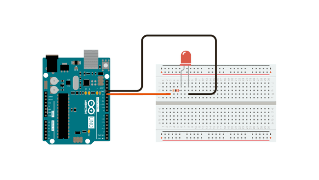
Circuit
The circuit for this project is simple yet essential for understanding how Arduino controls physical components. The LED is connected so that its anode (long leg) receives current from Arduino’s digital pin 13, while its cathode (short leg) is connected to the ground (GND). Between the LED and the pin, a 220Ω resistor is placed in series to limit the flow of current and prevent the LED from burning out. When pin 13 is set to HIGH (5V), current flows from the Arduino through the resistor and LED into ground, causing the LED to light up. When the pin is set to LOW (0V), no current flows and the LED turns off. This simple circuit demonstrates how Arduino can act as a switch, controlling whether current flows or not, and is the foundation of many more complex electronic projects.
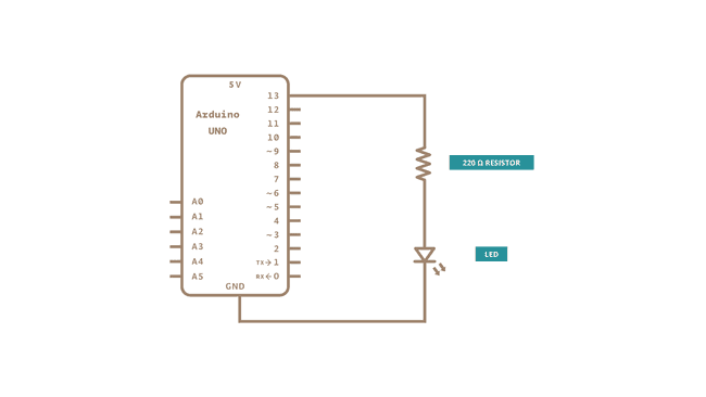
Schematic Diagram
The circuit for this project is simple yet essential for understanding how Arduino controls physical components. The LED is connected so that its anode (long leg) receives current from Arduino’s digital pin 13, while its cathode (short leg) is connected to the ground (GND). Between the LED and the pin, a 220Ω resistor is placed in series to limit the flow of current and prevent the LED from burning out. When pin 13 is set to HIGH (5V), current flows from the Arduino through the resistor and LED into ground, causing the LED to light up. When the pin is set to LOW (0V), no current flows and the LED turns off. This simple circuit demonstrates how Arduino can act as a switch, controlling whether current flows or not, and is the foundation of many more complex electronic projects.
Code with Step-by-Step Explanation
After you build the circuit, plug your Arduino board into your computer, start the Arduino Software (IDE), and enter the code below. You may also load it from the menu:
File → Examples → 01.Basics → Blink.
/*
Blink
Turns an LED on for one second, then off for one second, repeatedly.
*/

// Create a variable for the LED pin
int ledPin = 13; // Built-in LED pin on most Arduino boards

void setup() {
 // This runs once when you power or reset the board
 // Initialize pin 13 as an output pin
 pinMode(ledPin, OUTPUT);
}

void loop() {
 // This runs continuously in a loop

 digitalWrite(ledPin, HIGH); // Turn LED on (apply 5V)
 delay(1000);               // Wait 1 second (1000 ms)

 digitalWrite(ledPin, LOW); // Turn LED off (apply 0V)
 delay(1000);              // Wait 1 second
}
Line-by-Line Explanation
int ledPin = 13; → Defines the LED pin. Pin 13 is chosen because Arduino boards have an onboard LED
connected there.
• void setup() → Runs once at startup. The first thing you do is to initialize the LED pin as an output using:
pinMode(LED_BUILTIN, OUTPUT);
This allows the Arduino to send current to the LED.
• void loop() → Runs forever in a cycle.
• digitalWrite(ledPin, HIGH); → Supplies 5 volts to the LED’s anode. That creates a voltage difference across the LED and lights it up.
• delay(1000); → Waits for 1 second so the LED stays visibly ON.
• digitalWrite(ledPin, LOW); → Brings the pin back to 0 volts, turning the LED off.
• delay(1000); → Waits for another second with the LED OFF.
This sequence repeats endlessly, causing the LED to blink every second.


Hanna Ben
Inspiring education blog! Illuminating perspectives on effective teaching. Practical insights and innovative approaches make this a must-read for educators seeking impactful strategies. Bravo!
Mark Alen
Grateful for your kind words! Thrilled to hear you found value in the insights. Your support means a lot. Thanks!
Tom Hardy
Captivating education insights! This blog offers refreshing perspectives on effective teaching methods, making it a valuable resource for educators and learners alike. Well done!